Reading a KKnD2 Map
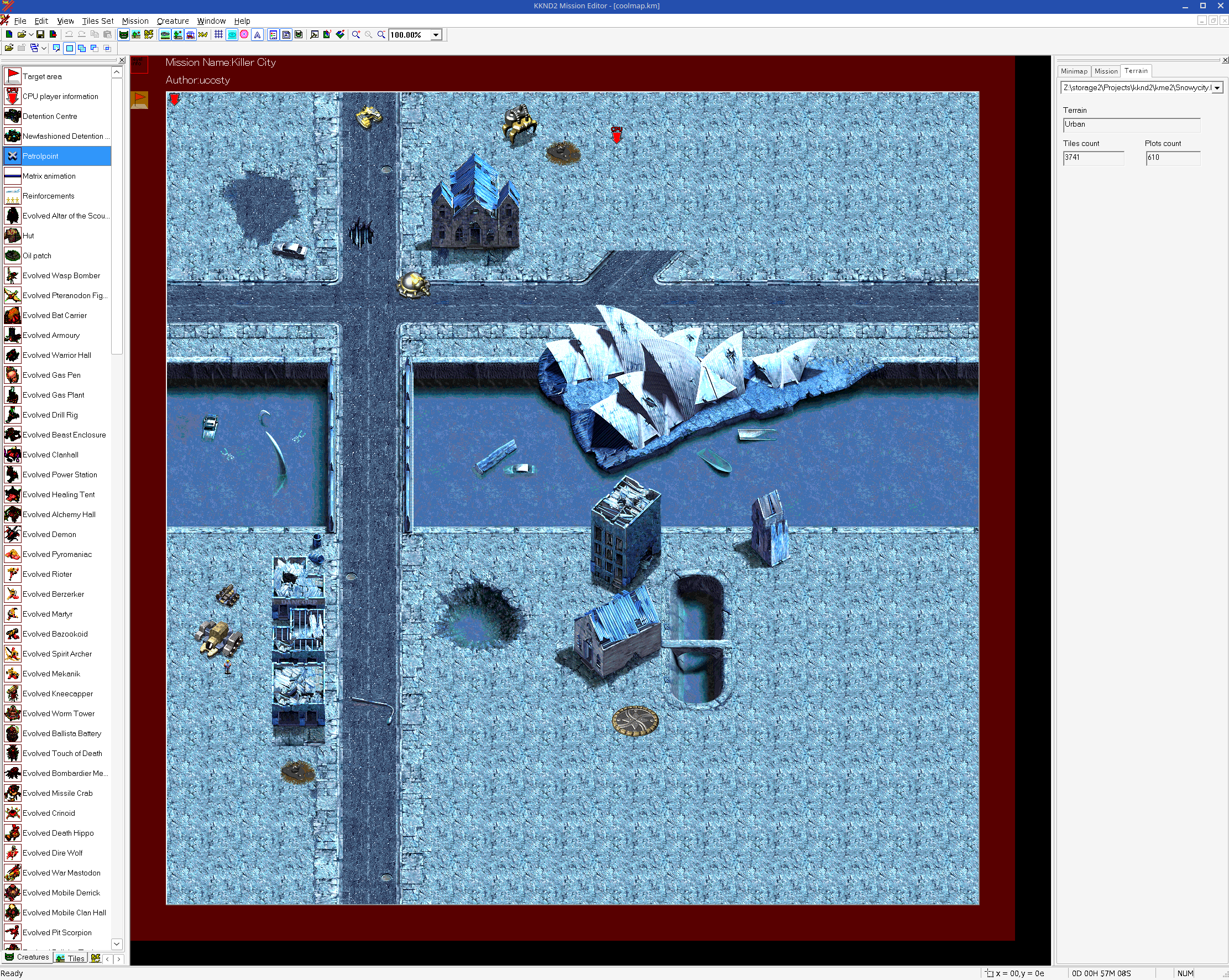
Continuing where we left off in part 1, we now have access to the contents of the game archives. I think it's time to work on understanding the game's map format. By the end we will be able to parse the game maps and even display them.
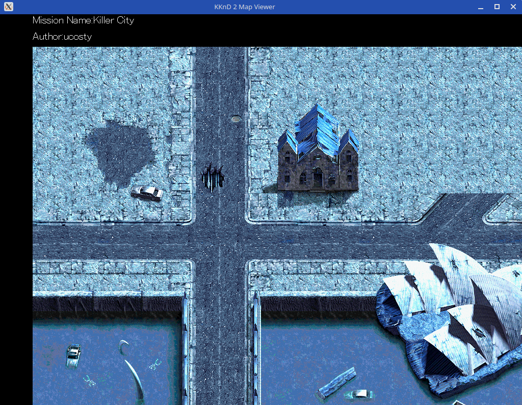
If you're only here for the code, you can find the resulting map viewer on Github at https://github.com/ucosty/kknd2-mapview. The UI is quite rough, but it works well enough to show that the map has been decoded.
To start, there were a number of options I had to decipher the map file format. I could
- Reverse engineer the game to see how it read the map contents
- Reverse engineer the map editor to see how it exported the map format
- Hack at the file directly, looking for things like offsets and patterns in data
I wound up using a combination of all three. Neither the game nor the map editor were easy to decipher on their own. At least I could control the map data I was looking at, by using the mission editor to create and export maps. These maps could then be decoded using the tools I made in part 1 and analysed.
First Look at the Map File
I have a few techniques to analyse binary files. Opening the file in a hex editor will give you an idea of the structure of a file. Binwalk's entropy mode can help you identify encrypted or compressed data. I also write one-off throwaway programs to read the binary data and hand parse it into structures, a form of printf analysis.

After creating a simple map in the mission editor I exported it, and then I unpacked the data using the kknd-unpack tool I wrote. This is a hex dump of the first 560 bytes of the file.
The first highlighted section (bytes 0 - 8) are the file header I added. Bytes 0 - 3 are a magic 0xdeadc0de used to identify this as an extracted resource file. Bytes 4 - 7 are the file's original offset within the map archive, in this case the offset was '4'.
The next two 32-bit words are '1' and '2', could be anything at this point. This is followed by two interesting numbers. Bytes 0x10 - 0x13 reads as the hex value 0x218. If you add the files offset you get 0x21c. Looking back at the hex dump, the data at offset 0x21c (the last 4 bytes on the row starting 00000210) is LRCS. Doing the same with the next 32-bit word (offsets 0x14 - 0x17) reveals another LRCS tag. This suggests that the earlier '2' (bytes 0xc - 0xf) is a count of the number of pointer entries exist. At this point it's all a guess.
What we have decoded so far looks like this:
+----------------------------+ 0x0
| Magic (0xdeadc0de)         |
| Orignal File offset (4)    |
+----------------------------+ 0x8
| 0x00000001                 |
+----------------------------+ 0xc
| Pointer count (2)          |
| Pointer to 0x218           |
| Pointer to 0x330c          |
+----------------------------| 0x18
|                            |
| 516 bytes of unknown data  |
|                            |
+----------------------------+ 0x21c
| 'LRCS' literal             |
+----------------------------+ 0x220
|                            |
| The rest of the file...    |
Taking a closer look at that 516 byte unknown section, starting at offset 0x18, I notice that the first 32-bit word contains the value 256 (0x100). Subtracting the size of this integer leaves 512 bytes of unknown data, or alternatively a 256-long array of 2-byte entries.
Map Layer Data
Starting from the LRCS tag, the data looks something like this:
+----------------------------+ 0x21c
| 'LRCS' literal             |
+----------------------------+ 0x220
| 32-bit word (32)           |
| 32-bit word (32)           |
| 32-bit word (50)           |
| 32-bit word (50)           |
+----------------------------+ 0x230
| 32-bit word (1600)         |
| 32-bit word (1600)         |
| 32-bit word (10568)        |
+----------------------------+ 0x23c
| The rest of the file...    |
I know that the map I made had a size of 50x50 tiles. I also know, from counting the pixels, that a tile is 32x32. It would be reasonable to assume that the first four values (0x220 - 0x230) are the tile size followed by the map size. By quickly making another map with different dimensions, I determined that the coordinates are specified as you'd expect, with width first. Putting that together, we end up with a layer header with the following structure:
+----------------------------+ 0x0
| 'LRCS' literal             |
+----------------------------+ 0x4
| Tile width in Pixels       |      -> value is 32
+----------------------------+ 0x8
| Tile height in Pixels      |      -> value is 32
+----------------------------+ 0xc
| Layer width in Tiles       |      -> value is 50
+----------------------------+ 0x10
| Layer height in Tiles      |      -> value is 50
+----------------------------+ 0x14
| Layer width in Pixels      |      -> value is 1600
+----------------------------+ 0x18
| Layer height in Pixel      |      -> value is 1600
+----------------------------+ 0x1c
| Offset to the attributes   |      -> value is 0x2948
+----------------------------+ 0x20
Between the end of the header and the start of the next 'LRCS' token, there are 12,500 bytes. That's a suspiciously nice and round number. The offset value sits 10,000 bytes into the 12,500 bytes of data. That divides up into:
- 10,000 bytes of tilemap data, or 50 x 50 x 4 bytes
- 2,500 bytes of attribute data, or 50 x 50 bytes
In a move that should feel totally familiar by now, each tile in the tilemap is an offset to the tile data within the map file. Blank tiles are represented by a zero value, and all other tiles point to a graphical tile.
Tile Graphics
Now we know (more or less) how the map is composed, the next thing we need to go about displaying it is to figure out the tile graphics format. Luckily there was a clue from earlier that helped a lot. We know that before the layer data there was a 256-entry table of values, contents unknown. This game comes from an era of games using 8-bit graphics composed together into a 16-bit framebuffer. If we assume that the 512-byte data is a palette, we can also assume each tile will be a 32x32 array of 8-bit values with each value corresponding to an entry in the palette.
To test this out, I wrote an application in Rust which decodes the map according to the logic above. You can find the code for this at https://github.com/ucosty/kknd2-mapview.

Each entry in the tilemap points to a 32x32 blob of raw pixel data. Each pixel value in those tiles points is an index into the palette from the start of the file. There are a few common ways to store colour information in a 16-bit format. Microsoft even have some documentation about a couple of 16-bit colour formats used in DirectShow, with a bit of code to convert between these formats and a standard 24-bit RGB format. After trying both RGB565 (5 bits of Red, 6 of Green, and 5 of blue) and RGB555 (5 bits of Red, Green and Blue), I found the graphics palette is stored in RGB555. There is also a special case, where palette entry 0 is reserved for transparent sections. This isn't useful on the base layer, but is used on the top layer extensively.
Batteries Not Included
As far as I can tell, this map file only contains the graphics and attribute tiles. The rest of the map information, such as unit and buildings, faction information, and other map metadata must be stored elsewhere.
Next, I'm going to take a look into the sprite graphics. Once I have those decoded, and I've found where the unit information is stored, I'd like to extend the map viewer to also display units and buildings.
Comments
There have been no comments made yet.
Submit a Comment